
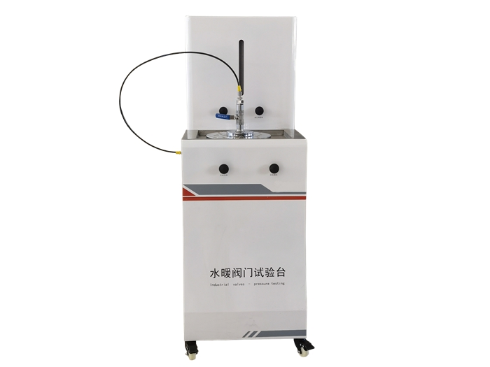
Water heating valve testing equipment
My company design and produce a variety of FM series general water heating valve testing equipment. Among them, FM-B valve testing equipment is a special testing equipment used with pipe test equipment, which has the advantages of small size, simple and reasonable structure, convenient operation and so on.
Application and scope of application
FM-B valve testing equipment is suitable for flanged valve and internal thread valve
Test for the following content:
- Shell test;
- Sealing test;
- Sealing test: the equipment is suitable for the test medium: water.
- Model description
- Model: FM-B
Structure
The testing equipment is mainly composed of:
- Operation table; 2. Leakage test cabinet; 3. Flange fixture; Test accessories and other compositions.
This equipment is used together with pipe pressure resistant equipment
- Operation table:
According to the provisions of the national standard, the valve should not be subjected to external forces that may affect the test results during the test. Therefore, the test bench adopts vertical installation of the specimen. The two ports of the specimen are sealed respectively, and there is no external force affecting the test results. It is convenient to install and easy to operate.
- Test cabinet:
The test cabinet is mainly used for the display of leakage. The reading is clearly intuitive.
configuration and parameter table
|
Number of test routes |
1 Way |
|
|
Flange base |
1 |
|
|
Pipe diameter range |
Flange type |
Diameter DN=10 to DN100㎜ (1/2 "to 4") |
|
Internal thread type |
Diameter DN=15 to DN100㎜ (1/2 "to 4") |
|
|
Test jig |
Flange type |
15,20,25,32,40,50,65,80,100 DN10, a set of each |
|
Internal thread type |
1/2 ", 3/4 ", 1 ", 1¼ ", 1½ ", 2 ", 2½ ", 3 ", 4 "each |
|
|
Pressure range |
PN=0 to 6MPa |
|
|
Amount of leakage |
0 to 10ml |
|
|
Minimum indexing value |
0.1 ml |
|
Description of the test item
1, test pressure: test, the specimen cavity should bear the calculation pressure.
The specific pressure value should be determined according to the nominal pressure index of the specimen and the corresponding national standards.
- Shell test:
For the valve, it refers to the pressure test of the whole valve shell formed by the valve body and the valve cover. The purpose is to test the tightness of the valve body and the valve cover and the pressure resistance of the whole shell including the valve body and the valve cover connection.
- Sealing test:
Test the sealing performance of opening and closing parts and valve sealing pairs (test pressure see relevant standards).
- Upper seal test: test the sealing performance of the valve stem and valve cover seal.
Five, operating rules
Valves for testing DN10 ~ 100mm(1/2 "~ 4") can be installed on the operating table.
- Mounting of flanged valves
Flange test AIDS (bottom) and valve flanges are bolted to the operating table (O-ring seal is used between flanges)
Screw the upper part of the valve flange with the test aid (top) through the bolts (seal between the flanges with O-rings). A quick change joint is fixed in the middle of the upper auxiliary.
- Installation of internal screw valve
The internal threaded valve test AIDS (with the lower thread fixed on the operating table. Screw the valve directly onto the thread of the lower accessory. (The thread should be sealed with a sealing tape wrapped around it). Screw the auxiliary (top) directly into the upper end of the valve. There is a quick change joint fixed in the middle of the upper auxiliary.
After the valve under test is installed, insert the high pressure hose into the quick change connector at the leak detection inlet.
Connect the water pressure source to the main pressure inlet of the equipment through the high pressure hose, and open the inlet pressure switch hand valve.
Six, test methods and steps
Generally, the upper sealing test and shell test are carried out first, and then the sealing experiment is carried out
1, the sealing test
In the case that the pipeline and the specimen have been connected well, the leakage detection switch is opened. The leakage and drainage switch is closed, and other valves are open.
Loosen the packing gland of the valve under test (if the valve is equipped with an upper seal check device). And if the performance of the upper seal can be reliably checked without loosening the packing gland, it is not necessary to relax the packing gland). The tested valve is in a fully open state, so that the upper seal is closed.
Open the pressure test pump, at this time the pressure water through the main pressure inlet, inlet pressure switch hand valve, test specimen, high pressure hose, leakage detection inlet, leakage detection switch hand valve, leakage pipe, the gas in the system is discharged first. When water is discharged from the leakage detection pipe, close the leakage detection switch, gradually pressurize to the specified test pressure, and continue for a period of time (according to the standard time), and then check the sealing performance.
- Shell test
After the above test, part of the pressure is discharged to press the packing gland in order to maintain the test pressure. The valve opening and closing parts are in a partially open state, gradually pressurize to the test pressure, and then check the shell (including the packing box and the connection between the valve body and the valve cover).
3, sealing test
First of all, the pressure test pump is in a low pressure operating state.
- Open the leakage detection switch hand valve to make the leakage pipe liquid level rise to a certain height
- Close the opening and closing parts of the tested valve tightly (with normal force)
- Open the leakage drain switch so that the leakage pipe liquid level is in a low position, and record the initial scale value of the liquid level after the liquid level is stable.
- Press to the specified pressure, continue for a certain time (according to the standard) to close the leakage drain switch, and record the scale value of the leakage pipe at the end.
- Evaluation index
- Shell test, upper seal test and seal test are all stipulated by GB/T13927 standard.
2, the calculation of liquid leakage:
The indicating value of the leakage of the testing equipment is 0.1ml for each small cell. If the liquid level rises to n cells, the total leakage is :V=0.1xn(ml).
Viii. Equipment maintenance and maintenance
The equipment belongs to no power source equipment, the pressure water used in the equipment is provided by the pressure pump of the pipe test equipment, so the maintenance is relatively simple.
- Often check whether the valve and its connection of the equipment leak, if there is leakage should be replaced in time.
- Keep the equipment clean and dry the water on the surface (the water leaked during the test).
- The water in the tank should be released frequently, especially in winter, to prevent freezing and cracking of the tank.
- After the test of leakage, the water in the glass tube should be released in time for the next test.


 冀公網(wǎng)安備 13080502000095號


